4 Wire Thermostat Wiring Color Code
/4 Wire Thermostat Wiring Color Code
If you are installing a smart thermostat like the Nest Thermostat or Ecobee Thermostat it’s important to know what the thermostat wiring Color codes are for the your new smart thermostat so that you wire the thermostat correctly.
Sometimes people forget to take a picture of the old thermostat wiring before they take it off or the labels can fall of the old wiring and it’s hard to determine what wire goes where for your smart thermostat. The following wiring conventions apply to both old style manual thermostats and smart thermostats but we highly recommend replacing your old thermostat with a smart thermostat because of how much energy and money you can save n the long run. The added wifi remote control of a smart thermostat is also a great upgrade to your home and can help you live more comfortably. Below we cover the 4 wire thermostat wiring color code.
4 Wire Thermostat Wiring Color Code
4 Wiring Thermostat Color Code For Nest Thermostat
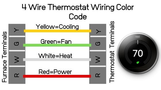
The picture above depeicts the typical wiring color code for a 4 wire thermostat. The above is a typical wiring diagram of a Nest Thermostat with 4 wires. This is commonly found in standard HVAC systems that use an air conditioner and a furnace.
Red Wire = Rh = Power
White Wire = W = Heating Wire
Yellow Wire = Y = Cooling Wire
Green Wire = G = Fan Wire
It should also be noted that sometimes a blue wire is used in lieu of a yellow wire for cooling depending on the brand of thermostat wire so you could have a situation where the blue wire is the cooling wire, if you only have 4 wires. If you have 5 wires for your Nest Thermostat the blue wire is most likely a common wire or heat pump reversing valve wire.
Blue Wire = Y = Cooling
4 Wire Thermostat Wiring Color Code: What does it mean?
So while we gave you the common thermostat wire color codes, and how they should be wired on your smart thermostat it’s important to know how a thermostat operates and works so that you can properly install your thermostat or troubleshoot if you run into issues.
A thermostat controls your HVAC system and it works almost like light switch, but just a smarter light switch that has some more circuitry in it.
The concept is that when you adjust your thermostat its like flipping a switch, and you are providing power to the your HVAC system to work, it’s just that in a typical 4 wire thermostat the thermostat decides where to route the power to turn on your HVAC system to make it heat, cool or run the fan.
So the Red Wire or R wire provides power to the thermostat and system for control. When it reaches the thermostat once you select weather you want heating or cooling or the fan to run the thermostat will then close the switch to that path, and if you were to chose cooling the power would run from the R wire though the W wire = White down to the furnace and activate the HVAC cooling system.
The R wire is the power and the other wires are the pathways to the HVAC system to control it.
4 Wire Thermostat Wiring Color Code: What Should I Know?
Well, we provided you with the most common thermostat wiring color codes and conventions but every now and then someone does a DIY job or just didn’t know what they were doing and uses different colors for different things and they don’t match up in the thermostat. If that is the case there is one way to determine what the right wiring is.
You can check the thermostat wiring with the following steps:
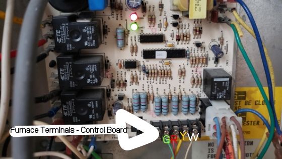
Inside your HVAC system there is a control board that will show you which wires are connected to which controls on the HVAC system. To access the HVAC system control board you need to turn off the HVAC system either with the switch on the side of the unit or at the control board.
Open the HVAC unit by removing either on or both covers.
On the control board there will be a set of terminals typically labeled “ R G Y W C “ and each of these terminals corresponds to the wires that should be routed to your thermostat, and control different parts of the furnace.
So even if they used the wrong color wiring, what ever wire is connected from R on the furnace terminal to R on the thermostat terminal will provide power. and whatever wire is connected from Y on the Y terminal of the furnace to the Y terminal on the thermostat will control cooling.
The conventions for each terminal are the same as previously listed above:
R on HVAC Terminal = Rh = Power = Rh on Thermostat
W on HVAC Terminal = White = W = Heating = W on Thermostat
Y on HVAC Terminal = Yellow = Y = Cooling = Y on Thermostat
G on HVAC Terminal = Green = G = Fan Wire = G on Thermostat
Make note of which wires are connected to which terminal in the HVAC control board and connect those wires to the matching terminal on the thermostat.
What happens if you connect the wrong wire, to the wrong terminal? Well sometimes nothing, sometimes your HVAC system will run unintentionally and sometimes your HVAC system will blow a fuse. But don’t worry it’s easy to replace furnace fuse if you blow it. Typically a 3AMP fuse like this will work and you just pull out the old fuse from the control board and replace it with the new fuse. You should always replace the old fuse with the same rating fuse. 3AMP is the most common and some furnaces use 5AMP fuses. Just remember to correct your wiring before replacing the fuse.
Below we have a video that explains thermostat wiring color codes and how thermostat wiring works in more depth.
What Else Should You Know About Smart Thermostat Wiring?
Smart thermostat’s are a great investment, just take your time when installing your new smart thermostat and you should be fine. The best thing to do is to take a picture before you start your project so you know what wiring was there.
If you choose a Nest Thermostat we highly recommend getting additional Nest Room Sensors so you can control your temperature in individual rooms.
We also teach you how you can control your Nest Thermostat with voice in another post using Alexa. But any Alexa Echo device when paired with Nest will allow you to control your Nest Thermostat with voice.


